Configure DHCP IPv4 on Cisco Layer 3 Switch or Multilayer Switch with 2 VLANs
In this tutorial, we will configure DHCP IPv4 on a Cisco Layer 3 Switch (or Multilayer Switch) to support two VLANs. The topology involves setting up two VLANs with different subnets and configuring DHCP pools for each VLAN.
Topology Overview
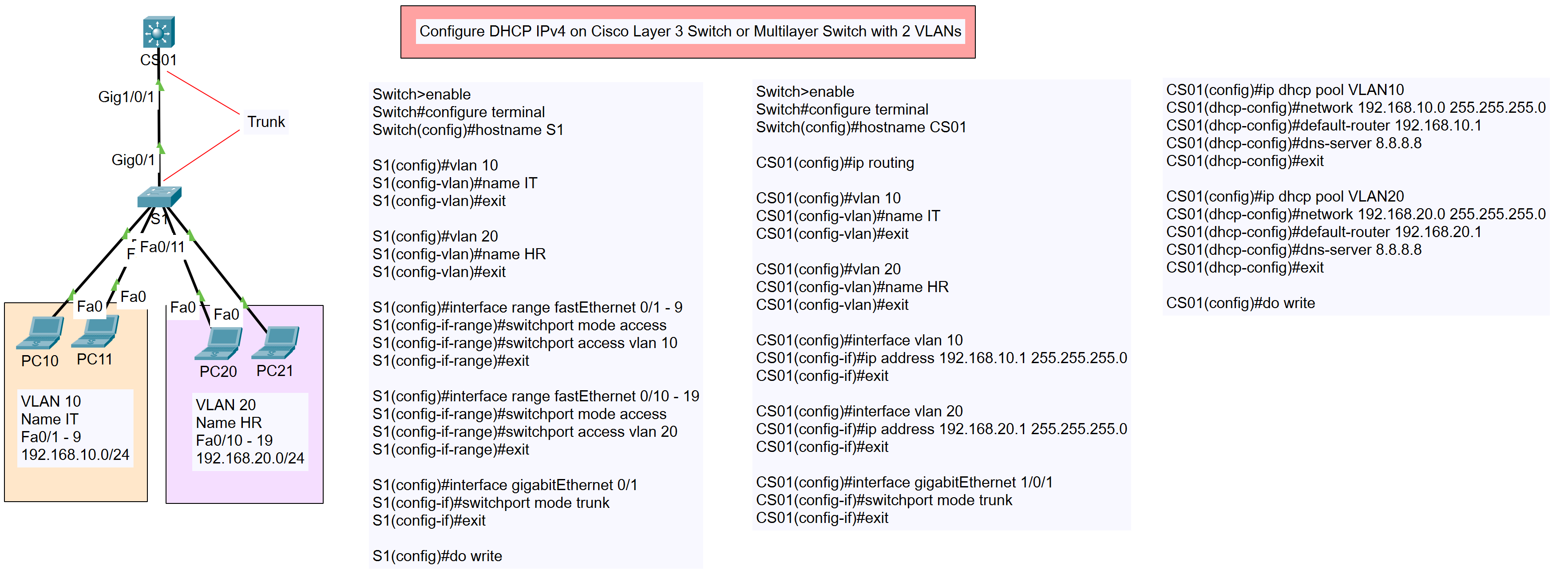
The network consists of:
- VLAN 10 (IT Department): 192.168.10.0/24
- PCs: PC10, PC11
- VLAN 20 (HR Department): 192.168.20.0/24
- PCs: PC20, PC21
- A Layer 3 Switch (S1) connected to a Core Switch (CS01) through trunk links.
Type of DHCP IPv4
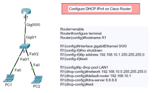
- DHCP IPv4 on Cisco Router
- DHCP IPv4 on Cisco Layer 3 Switch or Multilayer Switch
- DHCP IPv4 on Cisco Router with 2 Networks
- DHCP IPv4 on Cisco Layer 3 Switch or Multilayer Switch with 2 VLANs
Configuration Steps
- Configure VLANs on Switch S1
Switch>enable
Switch#configure terminal
Switch(config)#hostname S1
S1(config)#vlan 10
S1(config-vlan)#name IT
S1(config-vlan)#exit
S1(config)#vlan 20
S1(config-vlan)#name HR
S1(config-vlan)#exit
- Assign VLANs to Interfaces
S1(config)#interface range fastEthernet 0/1 - 9
S1(config-if-range)#switchport mode access
S1(config-if-range)#switchport access vlan 10
S1(config-if-range)#exit

S1(config)#interface range fastEthernet 0/10 - 19
S1(config-if-range)#switchport mode access
S1(config-if-range)#switchport access vlan 20
S1(config-if-range)#exit
- Configure Trunk Port
S1(config)#interface gigabitEthernet 1/0/1
S1(config-if)#switchport mode trunk
S1(config-if)#exit
- Enable Routing on the Core Switch (CS01)
CS01>enable
CS01#configure terminal
CS01(config)#hostname CS01
CS01(config)#ip routing
- Configure VLANs on CS01
CS01(config)#vlan 10
CS01(config-vlan)#name IT
CS01(config-vlan)#exit

CS01(config)#vlan 20
CS01(config-vlan)#name HR
CS01(config-vlan)#exit
- Assign IP Addresses to VLAN Interfaces
CS01(config)#interface vlan 10
CS01(config-if)#ip address 192.168.10.1 255.255.255.0
CS01(config-if)#exit

CS01(config)#interface vlan 20
CS01(config-if)#ip address 192.168.20.1 255.255.255.0
CS01(config-if)#exit
- Configure DHCP Pools on CS01DHCP Pool for VLAN 10
CS01(config)#ip dhcp pool VLAN10
CS01(dhcp-config)#network 192.168.10.0 255.255.255.0
CS01(dhcp-config)#default-router 192.168.10.1
CS01(dhcp-config)#dns-server 8.8.8.8
CS01(dhcp-config)#exit
DHCP Pool for VLAN 20
CS01(config)#ip dhcp pool VLAN20
CS01(dhcp-config)#network 192.168.20.0 255.255.255.0
CS01(dhcp-config)#default-router 192.168.20.1
CS01(dhcp-config)#dns-server 8.8.8.8
CS01(dhcp-config)#exit
- Save the Configuration
CS01(config)#do write
S1(config)#do write
Conclusion
By following the steps outlined above, you will have successfully configured DHCP IPv4 on a Cisco Layer 3 Switch with two VLANs. This setup ensures that devices in both the IT and HR departments receive IP addresses dynamically, simplifying network management.
If you have any questions or run into issues, feel free to leave a comment below!